
What is the difference between power splitter and coupler?
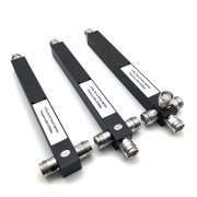
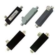
Power Splitter: A power splitter that equally divides the signal power of one port to output ports; Combiner: Power synthesis, adding two or more signals to one port; Coupler: proportionally couples the signal to the coupled port. The power splitter is used in turn to be a combiner. The coupler can be thought of as a type of power splitter, but it’s not equally divided.
Coupler: It is to distribute the input signal proportionally to multiple outputs. For example, 10 dB coupler, the input signal is 50dB, then the output signals are direct out and coupled output, respectively 50dB minus insertion loss, 40dB minus insertion loss.
Combiner: combines multiple input signals into one input.
1) In mobile communication, due to the sharing of multiple channels, in order to avoid intermodulation interference caused by RF coupling between different channels, and considering economic, technical and erection venue factors, the antenna should be used for transmission.
2) The combiner consists of a circulator and a cavity resonator, which is high-Q, low insertion loss bandpass filter. The circulator is a three-fault device with a small forward loss (0.8dB) and a large reverse loss (20dB).
3) In order to enhance the stability of the combiner work, the internal matching technology is now generally used to connect the cavity without a flexible cable. In order to reduce the volume, a square cavity structure is generally used.
Main technical indicators of the combiner:
1) Insertion loss, 4 channels are usually less than 3.6dB, and 8 channels are usually less than 4.0dB;
2) Inter-channel isolation, usually greater than 80dB;
3) Output and input port isolation, usually greater than 80 dB;
4) Frequency drift, usually not more than 3ppm after one year of aging;
5) Input standing wave ratio, less than 1.5dB.
Combiner test:
1) Insertion loss test;
2) Inter-channel isolation test;
3) VSWR test;
4) The test line of the above measurement network analyzer should be corrected.
The combiner is also divided into two types: the same frequency synthesizer and the different frequency combiner. For the combination (synthesis) of signals in the same frequency band, since the channel spacing is very small (250KHz), the resonant cavity frequency selection method cannot be used for combing, and a 3dB hybrid coupler is commonly used.
The 3dB hybrid coupler has two input ports and two output ports. After the two carriers are combined, the tow output ports can be used for signal output. If only one output signal is needed, the other output port needs load absorption. The power of the load is determined according to the power of the input signal, and can not be less than 1/2 of the power level of the two signals. It’s recommended to connect the two signals to the signal transmission cables in different routing directions, so as to avoid excessively cost. In general, the power splitter can also be used as a combiner. The difference is that the power capacity is different.
When the combiner is not connected to the 3G, but directly to 2G device, we need to turn off the 3G port. The load is what it does.
The load can be simply understood as a lossy device with very large losses. After the signal passes through the device, the attenuation may be very large.
The power splitter allocates the signal from the antenna received by the base station to multiple devices for processing. The coupler is for base station transmitting. It combines the carriers that are prepared to be transmitted by multiple devices into one channel and transmitted from the antenna. Generally, after being combined, the frequency is converted and amplified before reaching the antenna port.
The power splitter is one of the most common passive components used to divide a signal into multiple signals, which plays the role of equal power distribution. Commonly, there are two-way power splitter, three-way power splitter, and four-way power splitter. The reverse application of the power splitter becomes a combiner.
The coupler divides one signal into two signals that are not equal. The coupler has three terminals: the input, the through and the coupling. According to the power difference between the input and the coupling end, there are 5dB, 6dB, 7dB, 10dB, 15dB coupler etc. It can also be divided into 1:1, 2:1, 4:1 and the other models according to the ratio of the through and the coupling ends. Of course, both the power splitter and the coupler are lossy.
In the maintenance process, it is best not to replace each other, even if the couplers with different energy losses cannot be replaced by each other. In the construction, it is better to use the devices in strict accordance with the design, and do not arbitrarily replace each other.